Gas processing plants: sweetening, dehydration and NGLs
A unit-by-unit tour of a gas plant: slug catchers, amine towers, sulfur recovery, glycol contactors, the cold box, the demethanizer and the fractionation train.
 By Ingrid Solheim9 min read
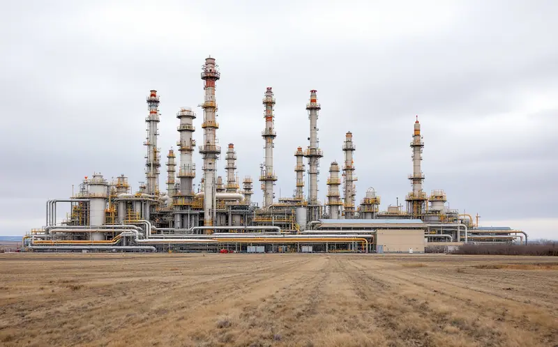
From the road, a gas plant looks like a small refinery that somebody tidied up and then forgot to finish. There are columns of different heights, long pipe racks, banks of air coolers with their fans turning, a few low buildings and a flare stack off to one side. It is hard to tell what any of it does from the fence.
It helps to know that nearly every piece of kit on the site is answering one question: what is in this gas that the pipeline will not accept, and what is in it that someone will pay for separately? Our overview of the natural gas value chain puts the plant in its place between the gathering system and the transmission line. This piece walks through the plant itself, unit by unit, in the order the gas meets them.
What arrives at the inlet
Raw gas from a gathering system is a mixture. Methane is most of it, but there are also heavier hydrocarbons (ethane, propane, butanes and the pentanes and heavier that the industry calls natural gasoline), water, and often carbon dioxide, hydrogen sulfide and nitrogen. In some fields there are traces of mercury or a useful amount of helium.
Every plant is designed around its own feed. A plant taking lean, sweet gas may be little more than a dehydration unit and a dew point control skid. A plant on a rich, sour gas stream will have every unit described below, and some of them twice.
The tour, unit by unit
Inlet separation and the slug catcher
Gathering lines do not deliver a steady, clean stream. Liquids collect in low spots and arrive in surges, called slugs, especially after a pig run or a change in flow. The first thing the gas meets is a slug catcher, which on a large plant is often a set of long, gently sloped pipes, sometimes called a finger-type catcher, and on smaller plants is a large vessel. It gives the liquids somewhere to settle.
Downstream, inlet separators split the stream three ways: gas off the top, hydrocarbon condensate in the middle, and water at the bottom. The condensate is stabilized and sold. The water is treated and disposed of, usually by injection into a disposal well where the rules allow it.
If the gas arrives at low pressure, inlet compressors raise it before the rest of the plant sees it, because many of the downstream units work better at higher pressure.
Sweetening: the amine unit
Gas with hydrogen sulfide in it is called sour. Pipelines will not take it, because hydrogen sulfide is toxic and it corrodes steel, and they limit carbon dioxide too. The usual answer is an amine unit, a pair of tall columns that is easy to spot on most plant layouts.
In the first column, the absorber or contactor, gas flows upward through trays or packing while a water-based amine solution flows down. The amine picks up hydrogen sulfide and carbon dioxide and leaves the bottom as rich amine. Sweet gas leaves the top. The rich amine then goes to the second column, the regenerator or stripper, where a reboiler at the bottom heats it until the acid gases come off overhead. The cleaned, or lean, amine is cooled and pumped back to the absorber.
Several amines are in common use, with names usually shortened to letters: MEA, DEA, MDEA and DGA among them. They differ in how strongly they grab hydrogen sulfide compared with carbon dioxide, and plants choose (or blend) them to suit their feed.
Anyone who has done hydrogen sulfide awareness training will recognize why the acid gas stream leaving the top of the regenerator gets so much respect. It is concentrated hydrogen sulfide and carbon dioxide, and it has to go somewhere safe.
Sulfur recovery
On a plant with enough hydrogen sulfide, that somewhere is a sulfur recovery unit, usually based on the Claus process. It works in two stages. In the thermal stage, a burner combusts about one third of the hydrogen sulfide to sulfur dioxide in a furnace, and a good share of the sulfur forms right there. In the catalytic stage, the remaining hydrogen sulfide and the sulfur dioxide react over a catalyst bed to make more elemental sulfur and water. Most units have two or three catalytic stages in a row, with condensers between them where liquid sulfur drains out.
What is left, the tail gas, still carries some sulfur compounds. Depending on the plant and its approvals, it goes to a tail gas treating unit that recovers more of them or to an incinerator. The liquid sulfur is either shipped molten or poured and left to solidify. The yellow blocks visible at some sour gas plants in Alberta are sulfur stored this way.
Dehydration: glycol or molecular sieve
Water vapor has to come out next. Wet gas can form hydrates, solid ice-like crystals that block valves and lines, and water with carbon dioxide or hydrogen sulfide in it is corrosive. Pipeline tariffs set a maximum water content for that reason.
The workhorse is a glycol unit, which looks and works much like the amine unit. Gas rises through a contactor while triethylene glycol (TEG) flows down and absorbs water. The wet glycol goes to a small regenerator, often called the still or reboiler, where heat drives the water off as steam. The dry glycol is cooled and pumped back up. The steam vent from a glycol still is one of the places operators watch for hydrocarbon emissions, a point our piece on methane leak detection and repair comes back to.
Glycol does not get gas dry enough for a cryogenic plant, where any remaining water would freeze. Those plants add molecular sieve beds, vessels packed with a granular adsorbent that pulls water out almost completely. The beds load up and are taken offline in turn and regenerated with hot gas, so you usually see two or three vessels side by side with a heater nearby.
Where the gas carries mercury, a guard bed takes it out before the cold section, because mercury attacks the aluminum used in many cryogenic heat exchangers.
The cold section: getting the liquids out
Now the gas is sweet and dry, but it still holds ethane, propane, butanes and heavier hydrocarbons that are worth more as liquids than as fuel, and that would condense in a pipeline if left in. The simplest way to drop them out is refrigeration: chill the gas with a propane refrigeration loop and the heavier components condense. That is enough for dew point control and for recovering much of the propane and heavier.
To recover ethane, plants go much colder with a turboexpander. Dry gas at high pressure is first cooled against cold outgoing gas in a brazed aluminum heat exchanger, the "cold box". Then it passes through the expander, a turbine in which the gas does work as it expands and its temperature drops sharply, far below what refrigeration alone can reach. The expander's shaft usually drives a compressor that recovers some of the pressure the gas lost.
The cold, partly liquid stream feeds a tall column called the demethanizer. Methane, with a little nitrogen, comes off the top as residue gas, the plant's main product. It is warmed, recompressed and sent to the transmission line. A mixed stream of ethane and heavier liquids leaves the bottom.
Plants can also run in what the US Energy Information Administration calls ethane rejection, leaving much of the ethane in the residue gas rather than recovering it, as long as the gas still meets pipeline specifications. Ethane raises the heat content of the gas above that of pure methane, which the EIA puts at about 1,010 Btu per standard cubic foot.
Fractionation
The mixed liquids stream, often called Y-grade or NGL mix in North America, is split into products by a train of distillation columns. Each column boils off the lightest component it is designed for and sends the rest to the next one.
- The deethanizer takes ethane off the top.
- The depropanizer takes propane off the top.
- The debutanizer takes the butanes off the top, leaving natural gasoline (pentanes plus) at the bottom.
- A butane splitter, where one is fitted, separates normal butane from isobutane.
Some large plants fractionate on site. Many others send the mixed liquids by pipeline to a central fractionation hub, which is why fractionators tend to cluster in a few places. The EIA's page on hydrocarbon gas liquids lists the main uses: feedstock for petrochemical plants, fuel for heating, cooking and drying, blending into motor gasoline, and diluent for moving heavy crude.
The plant at a glance
| Unit | What it removes or makes | What to look for on site |
|---|---|---|
| Slug catcher and inlet separators | Liquid surges, condensate, free water | Banks of sloped pipe or large horizontal vessels near the inlet |
| Amine unit | Hydrogen sulfide and carbon dioxide | Two tall columns side by side, with a reboiler on the second |
| Sulfur recovery unit | Elemental sulfur from the acid gas | Furnace, catalyst vessels, sulfur pits or block storage |
| Glycol unit | Water vapor | Contactor tower and a small still with a vent stack |
| Molecular sieve beds | Remaining traces of water | Two or three vessels side by side with a regeneration heater |
| Turboexpander and cold box | Ethane and heavier, as liquids | A boxed-in exchanger, a compact expander-compressor set |
| Demethanizer | Splits residue gas from liquids | The tallest slim column on the site |
| Fractionation train | Ethane, propane, butanes, natural gasoline | A row of columns of falling height |
| Residue compression | Restores pipeline pressure | Large compressor building near the outlet |
A worked example, with illustrative numbers
Say a plant takes in 100 million standard cubic feet a day of raw gas. Every number here is round and made up for the example, not typical of any real field.
- Suppose 2 percent of the inlet gas, by volume, is carbon dioxide and hydrogen sulfide. The amine unit removes it, so about 2 MMcf a day leaves the regenerator as acid gas.
- Suppose another 1 percent is water vapor that comes out in dehydration. That is about 1 MMcf a day.
- Suppose 7 percent is ethane and heavier hydrocarbons, and the cryogenic section recovers most of it. Say 6 MMcf a day worth of gas leaves as liquids.
That leaves roughly 91 MMcf a day of residue gas for the pipeline. The difference between the 100 that came in and the 91 that went out is what the industry calls shrink. The plant also burns some of its own gas as fuel for compressors and heaters, which shrinks the sales volume a little more.
Now run the plant in ethane rejection. Say half of that recovered 6 MMcf is ethane, and the plant leaves it in the gas instead. Residue gas rises to about 94 MMcf a day, the liquids stream falls, and the heat content of each cubic foot of residue gas goes up. The plant has not changed physically. It has changed how it runs the cold section and the demethanizer.
What the control room watches
The board operator's screen tracks a short list of quality numbers that decide whether the residue gas can go to the pipeline at all: hydrogen sulfide content, carbon dioxide content, water dew point, hydrocarbon dew point and heat content. Analyzers on the outlet sample the gas continuously. If any of them drift out of specification, the plant has to correct the problem or stop sending gas downstream, and the gas goes to recycle or, in some cases, to the flare until it is back in line.
That is the plant's real product. It is not methane in general, but methane clean enough, dry enough and lean enough that a pipeline company will sign for it at the meter. Everything between the slug catcher and that meter exists to make the signature possible.

Ingrid Solheim
Ingrid grew up in Stavanger and has lived on both sides of the North Sea. She covers natural gas, LNG and offshore work, with a soft spot for compressors and the ships that carry gas across oceans.